DARK FIRESORIGINS UNKNOWN

Author: Dark Fires

  • When a Bright UAP Overloads the Camera: Saturation, Blooming and Lost Detail

    When a Bright UAP Overloads the Camera: Saturation, Blooming and Lost Detail

    A brilliant white patch in a sky photograph is not necessarily a faithful outline of the thing that produced it. Before measuring its width or interpreting a glowing extension as structure, check whether the camera ran out of recording capacity in the brightest part of the image.

    The measurement has a ceiling

    Teledyne’s explanation of pixel saturation describes a finite charge capacity in each sensor pixel. Near that limit, the relationship between incoming light and recorded signal ceases to behave linearly. In sensors susceptible to blooming, excess charge can spread into neighboring pixels, producing a bright blob or streak. The manufacturer also describes anti-blooming structures designed to limit that spread.

    These are sensor behaviors, not proof that every bright spot has bloomed. The exact camera architecture matters. A washed-out patch should not be labeled a particular electronic artifact solely because it is white. It does, however, warn that the image may no longer preserve the source’s brightness differences or boundary faithfully.

    Exposure is part of the evidence

    Basler’s camera guidance specifically warns that excessive brightness can produce blooming and smear in CCD images. It also distinguishes exposure time, aperture and gain: a longer exposure collects more light; an open aperture admits more; gain amplifies the pixel readout, including noise. These controls can change the recorded appearance without changing the object.

    Our practical recommendation is to preserve the original recording and document those settings wherever available. For a repeatable light, compare carefully recorded shorter exposures with the original, while keeping framing and focus consistent. If an apparent extension shrinks or disappears as overexposure decreases, that is evidence about the imaging process worth investigating, not an automatic identification.

    What a white core cannot tell you

    Darkening an already clipped image does not recover detail that was never recorded. Nor does sharpening supply an independent measurement of an unseen edge. An enlarged, high-contrast crop may look more definite while retaining the same information gap.

    For a report, distinguish the measured image footprint from the proposed physical size. Keep unsaturated neighboring features and any exposure changes in view. If the central patch remains featureless in every available frame, say that the object’s internal detail is unresolved. This is a limit on what the picture supports, not a verdict for or against an unusual object.

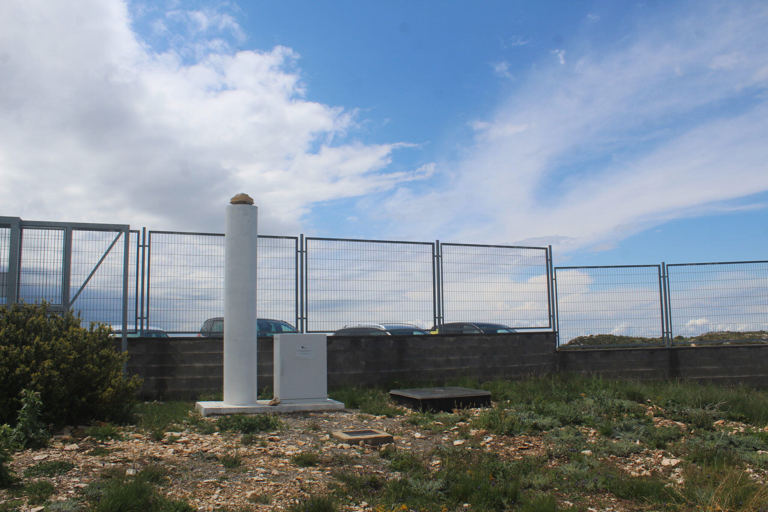
    Featured photograph: all-sky camera at Montsec, May 19, 2024. Contextual camera hardware, not a demonstration of saturation or a sighting. Credit: Castellgalie / Wikimedia Commons, CC BY 4.0; resized for display.

  • A Steady UAP Video Is Not Necessarily an Unprocessed Measurement

    A Steady UAP Video Is Not Necessarily an Unprocessed Measurement

    A smoothly centered light can make a sky video look like a stable measuring instrument. But image stabilization deliberately changes the relationship between camera movement and the recorded frames. Before calculating a UAP trajectory, establish what stabilized the picture, and when.

    Two different corrections

    In its March 2026 technical white paper, camera manufacturer Axis distinguishes optical stabilization, which moves an optical element to compensate for shaking, from electronic stabilization, which models motion and shifts the image using a margin of spare pixels. Image-based methods can have difficulty separating a moving subject from camera vibration. Gyroscope-assisted methods add an independent motion measurement. These are different systems, not one universal filter.

    The distinction matters especially at long zoom settings, where a small camera rotation produces a larger displacement in the picture. A visually calm output does not imply that the camera itself stayed still. Conversely, a moving light is not automatically a stabilization artifact. The processing history is a variable to investigate, not a ready-made explanation.

    A practical comparison

    Our suggested evidence check is to preserve the original file and make any stabilized copy separately. Ask the recorder for the exact camera or phone model, recording mode and stabilization setting, and whether an editor or social platform later stabilized or cropped the clip. Keep the untrimmed beginning and ending: changes in framing can be easier to see outside the dramatic moment.

    Then compare the target with stationary landmarks across several frames. If the horizon, roofline and light shift together, camera movement or a frame-wide correction deserves attention. If only the light changes position relative to those references, that is a different observation. Neither pattern alone identifies the object, and distant clouds are not necessarily stationary reference points.

    What not to claim

    Do not turn pixel displacement in a stabilized crop directly into physical acceleration. A defensible measurement needs the viewing geometry, frame timing and the transformations applied to the image. If the original cannot be recovered, state that limitation instead of presenting a processed trajectory as raw sensor data.

    This guide is an application of camera-engineering principles, not a finding about any particular sighting. Stabilization is valuable for seeing a scene clearly. Its usefulness as a viewing aid is precisely why an investigator should document it before treating the resulting frames as measurements.

    Featured photograph: all-sky camera at Montsec, May 19, 2024. Contextual camera hardware, not a demonstration of a stabilization system or a sighting. Credit: Castellgalie / Wikimedia Commons, CC BY 4.0; resized for display.
  • Alderney, 2007: Strong Witness Records Do Not Turn an Estimated Size Into a Measurement

    Alderney, 2007: Strong Witness Records Do Not Turn an Estimated Size Into a Measurement

    The Channel Islands sighting of 23 April 2007 is worth revisiting precisely because it has more than a dramatic recollection. Radio exchanges, flight information and written accounts allow parts of the sequence to be checked. They do not, however, justify treating every later headline as an instrument reading.

    The record behind the story

    In their original investigation, Jean-François Baure, David Clarke, Paul Fuller and Martin Shough describe airline pilot Ray Bowyer observing bright yellow forms while approaching Alderney. Passengers and a pilot aboard a separate aircraft also reported observations. The investigators drew on air-traffic-control recordings, radar material, Civil Aviation Authority documents and interviews. Their paper appeared in the Journal of Scientific Exploration, volume 22, issue 3, in 2008; the journal website’s later citation date should not be mistaken for the event date.

    The researchers explicitly rejected widespread claims that radar had established mile-wide objects. They found no unambiguous radar corroboration of the visual phenomena. They also cautioned that radar processing and sampling limited what a negative result could establish. Their study did not reach a conclusive identification. Atmospheric optics and an earthquake-related hypothesis remained possibilities, not demonstrated explanations. Read the original investigation.

    Separate three different questions

    Did people report an unusual sight? What physical phenomenon produced it? How large was that phenomenon? Those are separate questions. A contemporaneous recording strengthens the timeline and preserves what a witness said before later retelling. It does not automatically validate the witness’s distance estimate.

    That distinction changes the weight of a size claim. An angular extent becomes a physical dimension only after distance is established. Assigning a distant location and then calculating a large size cannot independently prove that distant location. A model may be internally consistent without being the only model that fits.

    The useful lesson is not to discard witnesses or to declare the case solved. It is to preserve the different evidence streams without promoting one into another: testimony is testimony; a radar return needs a justified association; a reconstruction carries assumptions. Alderney remains an instructive record of serious investigation that narrowed claims without delivering a definitive identity.

    Featured image: Generated illustration. Generic archival research artwork created for Dark Fires, not a sighting photograph or an official case document.

  • Euclid Opens Its DR1-Foundation Archive: A Billion Objects, Not a Finished Dark-Universe Answer

    Euclid Opens Its DR1-Foundation Archive: A Billion Objects, Not a Finished Dark-Universe Answer

    Euclid’s November 12, 2026 data release is a change in scale, not a declaration that dark matter or dark energy has been solved. DR1-Foundation makes a vast new observing record available for scientists to test: images, catalogues and spectra that can support many investigations beyond the striking pictures.

    ESA’s release announcement describes roughly 13 months of observations, including more than 900 million galaxies and spectra for over 160 million sources. The Wide Survey coverage is about 1,900 square degrees. Among the catalogues are around 15,000 strong-gravitational-lens candidates and more than 60 million quasar candidates.

    Why the word candidate matters

    Candidate lists are starting points for analysis, not a promise that every entry will survive follow-up scrutiny. Strong lenses are systems in which foreground mass distorts the light of a background galaxy. A much larger, consistently collected sample can let astronomers study populations rather than isolated curiosities. It is still necessary to separate genuine systems from lookalikes and understand how the search selected them.

    Foundation first, complete release later

    The IPAC archive record for the Wide Survey galaxy-candidate redshift catalogue confirms that DR1 is being released in two stages. Foundation was released November 12; the complete release is expected in mid-2027 and will add higher-level products for galaxy clustering and weak-lensing studies. IPAC also notes that DR1 supersedes the earlier Q1 release and includes observations of deep and calibration fields alongside the wide survey.

    That distinction is useful when judging announcements. Access to measurements is one milestone. Deriving robust distances, testing calibration, checking selection effects and comparing the resulting maps with cosmological models are further steps. A large catalogue gives those analyses statistical power; size alone does not settle the interpretation.

    A picture inside the larger survey

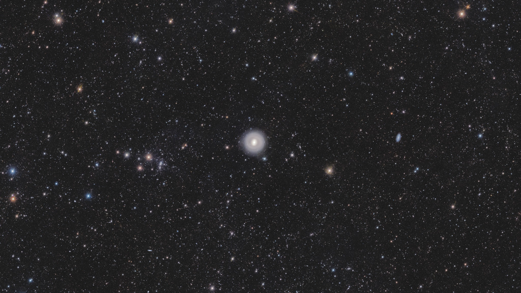
    The featured Euclid view of NGC 1291 illustrates the survey’s breadth. Released with this batch, it covers about 14 square degrees and took roughly a day and a half to acquire. The conspicuous nearby ring galaxy sits amid numerous smaller background objects: the visually dominant target is only part of the scientific content.

    The immediate opportunity is therefore concrete: researchers can work with the new archive now. Claims that this release has already delivered the final three-dimensional cosmic map, or identified the nature of dark energy, would go beyond what was announced.

    Featured image: NGC 1291 field from Euclid DR1-Foundation. ESA/Euclid/Euclid Consortium/NASA; image processing J.-C. Cuillandre and E. Bertin. CC BY-SA 3.0 IGO. Observational image, not generated artwork.

  • BepiColombo Nears Mercury Capture, but Its Full Science Campaign Comes Later

    BepiColombo Nears Mercury Capture, but Its Full Science Campaign Comes Later

    BepiColombo’s next major milestone is approaching: Mercury orbit insertion is scheduled for November 21, 2026. That is an upcoming maneuver, not an accomplished arrival. It also should not be confused with the start of the mission’s full scientific campaign.

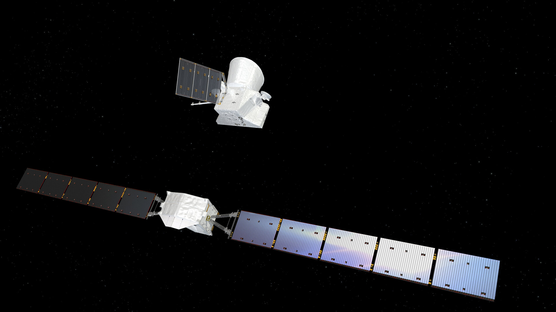
    ESA’s arrival updates set out a staged sequence. The Mercury Transfer Module separated on September 3. The still-connected European and Japanese orbiters are to be captured together, separate on December 9–10, and begin the science phase in April 2027. Those dates describe the current plan; each operational step still needs confirmation.

    Readiness is more than reaching the planet

    ESA’s October 6 update describes September 15 instrument tests after the transfer module’s departure. BELA, the laser altimeter, fired more than 700,000 pulses during a 21.5-hour test. MERTIS tested its now-unobstructed planet-viewing port alongside its calibration port. The SIMBIO-SYS camera system activated all three optical channels. The initial assessments were encouraging, but these were readiness tests, not the completed Mercury survey.

    Two orbiters, different jobs

    NASA’s mission overview explains the complementary design: ESA’s Mercury Planetary Orbiter will study the surface and interior, while JAXA’s Mio focuses on Mercury’s magnetic environment. Two vantage points let the mission investigate the planet and its surroundings together rather than asking one orbit to serve every measurement.

    The spacecraft launched on October 20, 2018. Their long approach is not evidence of inactivity: the journey has included planetary gravity-assist encounters and observations during Mercury flybys. But brief passes and sustained orbital measurements answer different questions. Orbiting permits repeated coverage and the systematic measurement program for which the spacecraft were built.

    Mercury is not wholly unexplored. Mariner 10 made three flybys in 1974–1975, and MESSENGER orbited from 2011 to 2015, revealing surface composition, geology, magnetic-field properties and polar water-ice deposits. BepiColombo extends that record with a coordinated European-Japanese observatory.

    What to watch next

    The immediate question is operational: has the planned capture succeeded? After that come separation, orbital adjustments and commissioning. Healthy instrument tests are reason for confidence, but they do not make later milestones automatic. Keeping those stages separate will make the arrival coverage easier to follow, and keep a scheduled achievement from becoming a premature headline.

    Featured image: artist’s impression of transfer-module separation, created in 2018; not a photograph of the 2026 event. ESA/ATG medialab, ESA Standard Licence.

  • Before the sighting: why dark adaptation belongs in a UAP report

    Before the sighting: why dark adaptation belongs in a UAP report

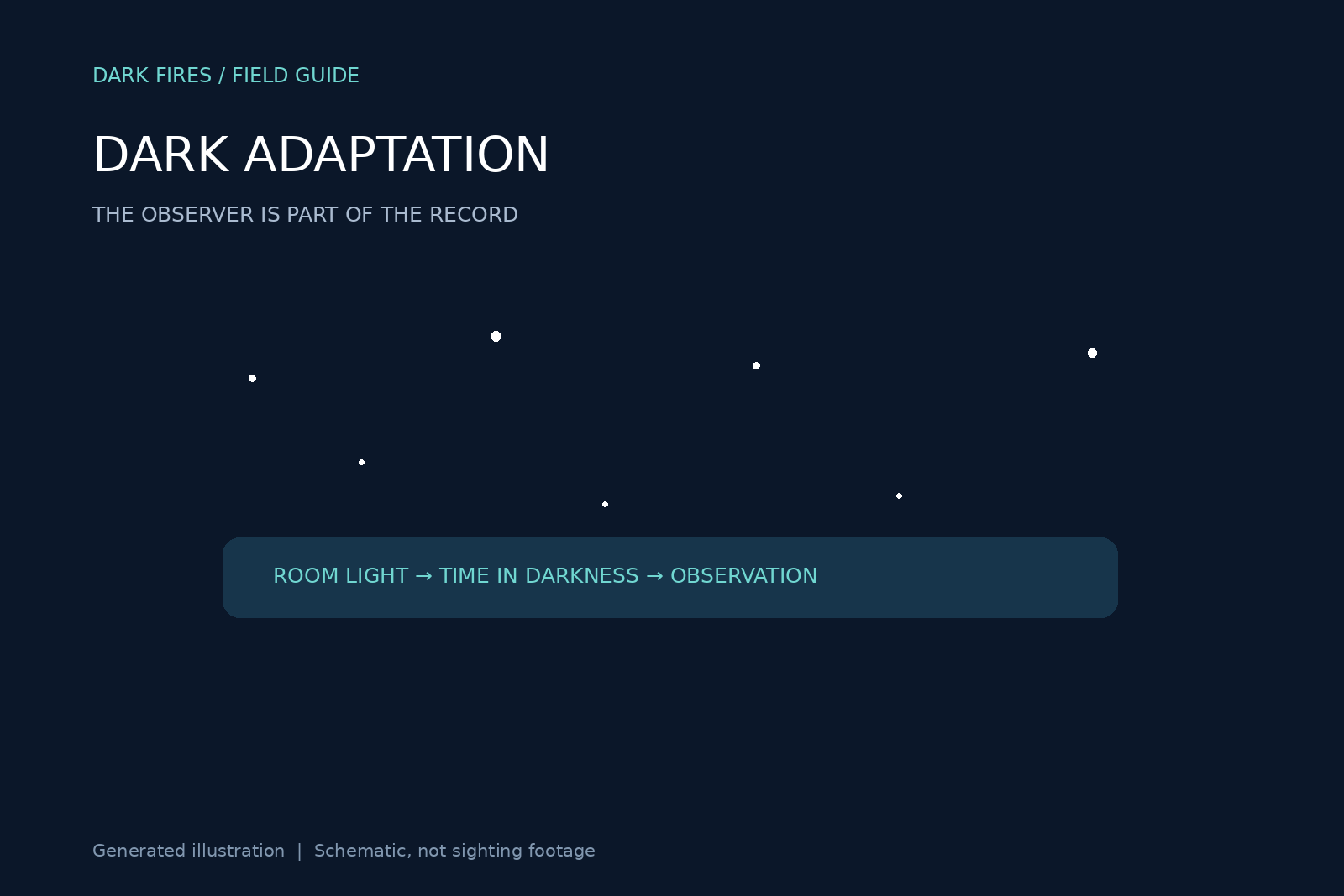
    A night-sky report often begins when a light is first noticed. For evidence review, the preceding minutes can be just as important. Someone who has been outdoors in darkness and someone who has just left a brightly lit room are not necessarily observing with the same sensitivity to faint light.

    Visibility changes without the sky changing

    The FAA’s Aeronautical Information Manual, section 8-1-6, describes dark adaptation as increasing sensitivity in darkness. Its guidance allows at least 30 minutes in total darkness for complete adaptation and notes that bright light can rapidly impair it. The same section explains that illumination and scanning technique affect what an observer can see.

    That does not make a witness unreliable. It means the observer’s recent lighting conditions are part of the observation. A newly visible faint point could reflect a change in the object, the atmosphere, attention or visual sensitivity. The first appearance in testimony alone does not choose among those explanations.

    Ask about the minutes before, not just the object

    For UAP documentation, we suggest a short, neutral sequence of questions: Had the observer recently come outdoors? Were porch lights, headlights or interior lights nearby? Was a phone screen or flashlight used immediately before the light disappeared or returned? Did the observer look continuously or alternate between the sky and a display?

    Record the answers without coaching. “Looked down at phone, then could not relocate the point” is useful detail. Rewriting it as either “the object vanished instantly” or “the phone caused the disappearance” goes beyond what was established. Preserve the observed sequence and keep proposed explanations separate.

    Two people are not two identical detectors

    If one person saw a faint light and another did not, compare their positions, obstructions and recent lighting exposure before treating the disagreement as a contradiction. A witness who joined later may also have looked at a different patch of sky. These possibilities are worth checking, not reasons to disregard testimony.

    Camera footage supplies another record but does not reproduce the eye’s adaptation state. A phone may change exposure while its user looks away; the resulting clip and the person’s account should be analyzed on their own terms before being combined.

    The practical takeaway is modest: add a lighting-history field to a nighttime report. This does not diagnose a witness or resolve a sighting by itself. It gives later reviewers a way to test whether an apparent onset, disappearance or disagreement might involve the observer’s conditions as well as the external scene. A case with that context is more useful than one with confident conclusions and missing circumstances.

    Featured image: original Dark Fires schematic. Generated illustration; not an observation or sighting photograph.

  • One radar return, several objects? Why resolution matters

    One radar return, several objects? Why resolution matters

    A radar plot is not a photograph of a collection of objects. When a UAP account says one return became several, an important preliminary question is whether the instrument could resolve the returns separately at both moments. Changes in the displayed count need not mean that a physical object split apart.

    A beam covers a volume

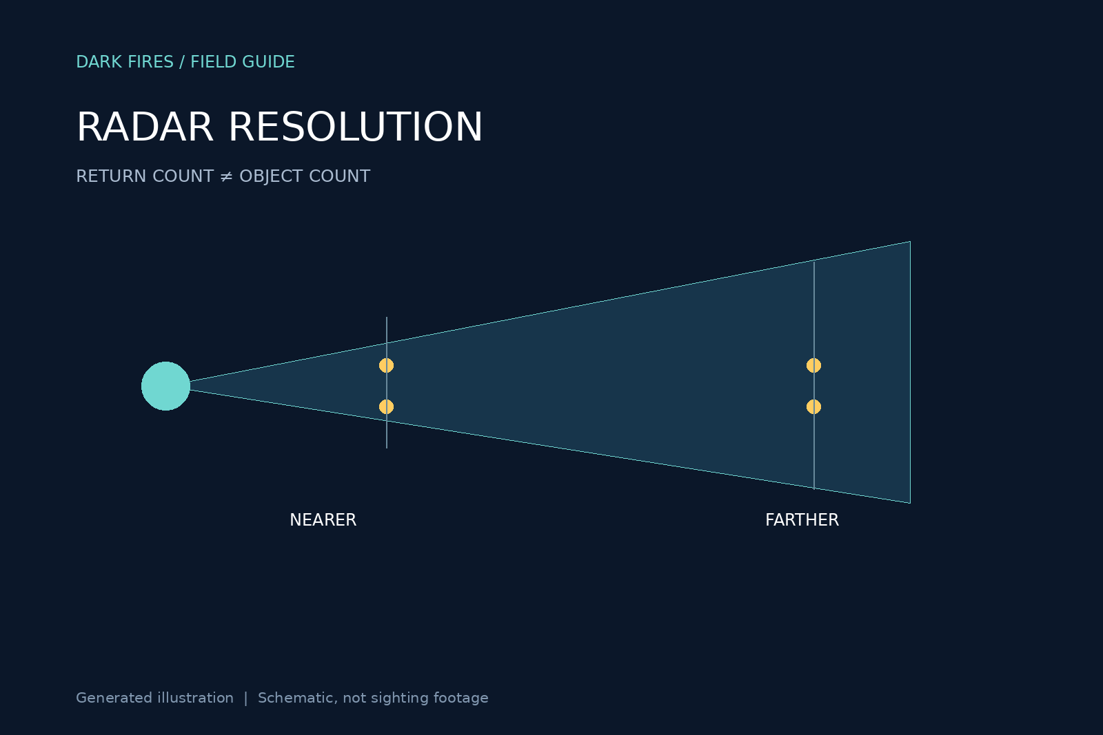
    NOAA’s explanation of radar beams describes a beam whose intensity fades outward rather than ending at a hard edge. It also widens with distance. NOAA illustrates the consequence with weather radar: small-scale features can merge or disappear from view when they lie farther from the instrument.

    The page gives a beam width of roughly one degree for WSR-88D weather radar and compares views of the same storm from different distances. Those are specifications and examples for that radar system, not measurements of a military sensor in a UAP case. Transferring them to an unidentified instrument would introduce false precision.

    Separation has more than one dimension

    Radar needs enough discrimination in direction and range to distinguish nearby reflectors. The National Weather Service’s basic radar principles training discusses pulse characteristics, pulse volume and target resolution. Two echoes may overlap in one dimension even if they differ in another. The displayed picture also depends on what processing preserves or combines.

    For a reader assessing a UAP claim, the key distinction is between objects, echoes, detections and tracks. An echo is received energy; a detection is a decision that a signal meets a criterion; a track associates detections across time. These terms should not be used as interchangeable counts of physical vehicles.

    What an informative release would contain

    Our suggested evidence request starts with the radar type and operating mode, observation ranges, beam or angular resolution, range resolution, scan times and display-processing details. Ask whether the “split” is visible in underlying detections or only in a processed animation. Preserve original timestamps and track identifiers, including any gaps.

    A useful test compares the claimed separation with the instrument’s resolving capability at that range. Another checks whether the display scale, threshold or tracking state changed near the apparent event. These are questions for the record, not assumptions about what a particular operator did.

    Resolution limits do not prove that a report is mistaken, and they do not explain every change in a track. If a suitably documented system resolves independent returns well beyond its uncertainties, that is stronger evidence than an ambiguous display alone. Even then, the returns’ physical identity remains a separate question. A count becomes meaningful only when the measurement process behind it is known.

    Featured image: original Dark Fires schematic. Generated illustration; not an observation or sighting photograph.

  • Simons Array Pushes a Search for Circularly Polarized Cosmic Light to Smaller Scales

    Simons Array Pushes a Search for Circularly Polarized Cosmic Light to Smaller Scales

    A new Simons Array analysis expands a difficult search in the oldest observable light: circular polarization in the cosmic microwave background. The result is not a detection. It is a set of upper limits, together with an instrument-and-analysis method that could make future searches more capable.

    The POLARBEAR Collaboration preprint, submitted November 9, 2026, reports observations at 90 gigahertz with the POLARBEAR-2b receiver in Chile’s Atacama Desert. It has been submitted to the Astrophysical Journal; the preprint should not be confused with a completed peer-reviewed publication.

    A different kind of polarization

    Most cosmic-microwave-background polarization work measures linear polarization, commonly described through E and B patterns. Circular polarization instead describes radiation whose electric field rotates as the wave travels. In this context the sought-after sky pattern is called a V mode.

    The standard cosmological picture does not predict an appreciable primordial circular-polarization signal. But several processes could generate a small one, including conversion of existing polarization as radiation passes through magnetized plasma. More speculative mechanisms also exist. A search therefore has scientific value without requiring a claim that new physics has appeared.

    What this measurement adds

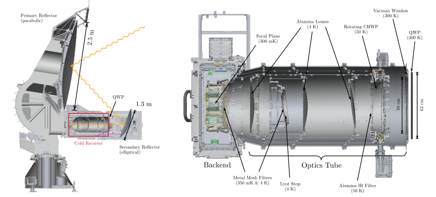
    The team combines a stationary quarter-wave plate with a rotating half-wave plate, allowing the receiver to recover information about circular polarization. Its analysis covers angular scales of roughly 5.4 to 36 arcminutes, corresponding to multipoles 300 through 2000. The authors describe this as roughly tripling the highest multipole previously reached in a V-mode power-spectrum measurement: smaller angular structures are now being tested.

    The observations amount to about two and a half months on each of two fields away from the Galactic plane, with an effective combined area near 12 square degrees. The published 95% upper bounds on the scaled polarization power range from about 22 square microkelvin at the largest analyzed scales to about 3,500 square microkelvin near the smallest. These are limits on a statistical power spectrum, not temperatures of individual celestial objects.

    Why a non-detection still needs caveats

    The analysis accounts for known foreground contamination rather than simply treating everything measured as cosmological. The paper also reports substantial instrument limitations: the receiver’s on-sky sensitivity fell short of its original target, and the added quarter-wave plate reduces transmission. The resulting limits are consequently constrained by the actual apparatus, not just by how much sky was observed.

    This distinction keeps the conclusion proportional to the evidence. The result does not establish that circular polarization is absent everywhere, nor does it discriminate among all proposed generation mechanisms. It tests a specified frequency and range of angular scales at a stated sensitivity.

    The practical advance is a reproducible route for extending the search. More sensitive observations and independent implementations can turn a currently weakly measured property of the microwave sky into a more useful probe. For now, the new boundary on what remains unseen is the finding.

    Featured diagram: POLARBEAR-2b optical layout, Figure 1 from the POLARBEAR Collaboration paper, CC BY 4.0. Instrument schematic, not an image of a detected sky signal.

  • The 1951 Ehrke Photograph: Why an Air Force File Is Not an Authentication

    The 1951 Ehrke Photograph: Why an Air Force File Is Not an Authentication

    A photograph in an Air Force flying-disc file can look more authoritative once it appears on a government website. Albert Ehrke’s 1951 submission is a useful antidote to that shortcut: the accompanying letter is skeptical, secondhand and more informative about provenance than about the object’s identity.

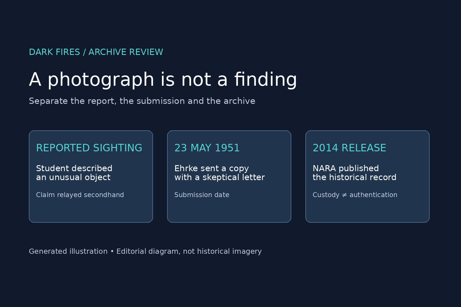
    This is a review of an existing historical record. The letter is dated 23 May 1951. The National Archives published its discussion on 28 March 2014; neither date should be mistaken for a precisely established sighting date.

    Read the letter before the picture

    In the scanned letter, Ehrke says he met a young man while attending Fullerton Junior College during 1949–50. That man reportedly watched an unusual flying object northwest of Fullerton and obtained two pictures. Ehrke says he acquired copies and sent one to the Air Force.

    That is a chain of reporting, not a direct eyewitness account by the correspondent. The letter attributes the sighting and photography to someone else. It does not supply the original photographer’s name, an exact observation time, an exposure record or a measured distance to the subject.

    Ehrke says the submitted picture was taken with infrared film and the other with ordinary film. He also repeatedly calls the pictures fake and suggests a research balloon. Those are his descriptions and suspicions, not a laboratory result proving either fabrication or a balloon identification.

    What the archive establishes

    The National Archives’ 2014 article places the material in Air Force intelligence correspondence, Record Group 341, box 293, in a folder covering flying discs in 1951. It provides both the letter and the associated image scan. The archival citation gives a reproducible route to the record. It does not certify the photographic subject as a craft or validate the correspondent’s proposed explanation.

    The letter also carries an office notation that a reply was unnecessary. That is evidence about administrative handling, not a technical analysis. The published material reviewed here does not include a demonstrated reconstruction of how the image was made.

    Two errors to avoid

    It would be wrong to present this as an Air Force-confirmed extraordinary object. It would also be wrong to claim that the sarcastic tone alone proves a hoax. A writer’s confidence and the evidential strength of a photograph are separate questions.

    A useful follow-up would seek the original negatives, the photographer’s account, camera and film details, and any contemporary analysis. Without those, the responsible conclusion stays limited: an authentic archival submission can preserve an unverified claim. Government custody establishes where the document survived, not what was in the sky.

    Featured image: original Dark Fires editorial diagram, AI-authored; Generated illustration. No simulated sighting or fabricated historical document is shown.

  • Which north? The bearing-reference problem in UAP reports

    Which north? The bearing-reference problem in UAP reports

    Two witnesses can report different compass directions while looking at the same part of the sky. Before drawing intersecting sight lines on a map, a UAP investigation needs to answer a deceptively small question: what did each person mean by north?

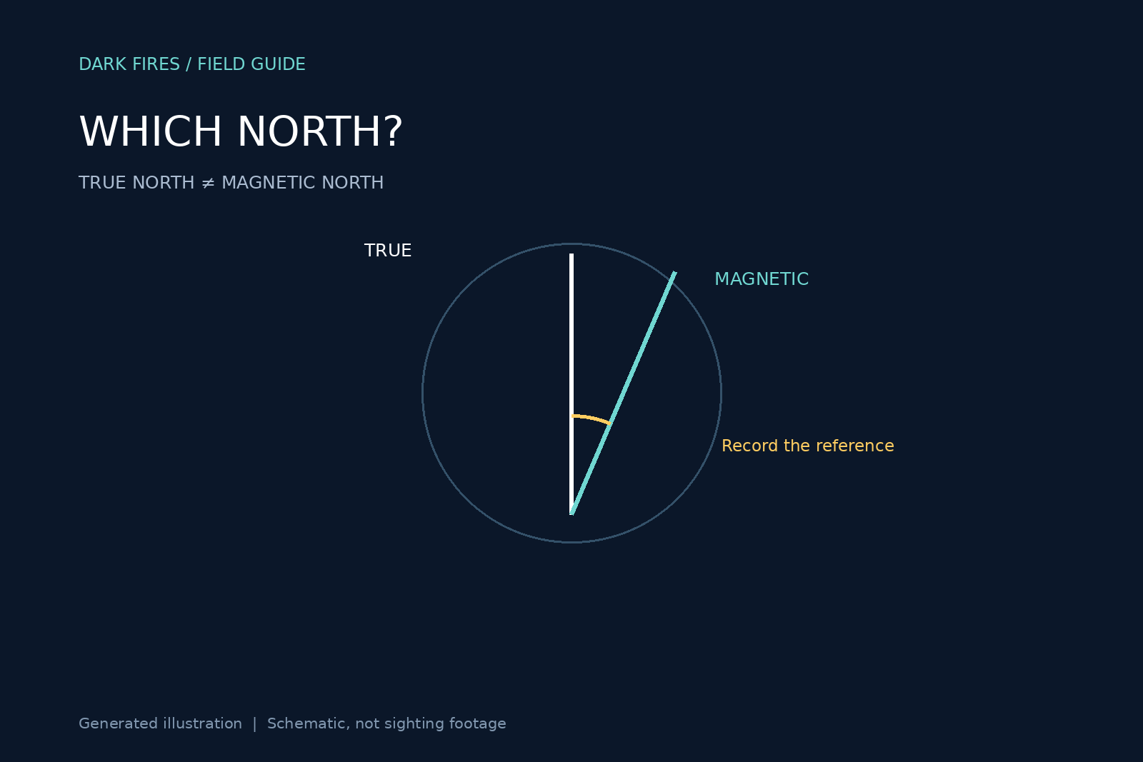
    True north is not magnetic north

    NOAA’s magnetic-declination guide defines declination as the angle between magnetic and true north. The correction varies with location and time. A magnetic compass responds to the local magnetic field; it is not simply an arrow pointing toward one fixed spot on a map.

    NOAA uses positive values for easterly declination and negative values for westerly declination. With that convention, true bearing equals magnetic bearing plus declination, wrapping the result into the 0–360-degree circle. In a purely hypothetical example, a magnetic bearing of 80 degrees at a place with 10 degrees east declination becomes 90 degrees true. This is arithmetic illustrating the convention, not a correction for any real sighting.

    The date belongs with the correction

    The USGS explanation of declination notes that a topographic map’s declination information applies to the map’s stated location and year. An old map margin is therefore not automatically the right correction for a recent report. NOAA provides a location-and-date declination calculator for a more explicit estimate.

    A phone readout adds a separate documentation problem. The investigator should record the app, its north-reference setting and the displayed number rather than infer the setting from the word “compass.” If a bearing was already expressed relative to true north, adding declination again creates a new error. A measured bearing should also not be silently substituted for a witness’s rough description such as “northeast.”

    Keep the original and normalized values

    Our suggested reporting format has six fields: original bearing; stated reference; observing location; date and time; correction source; normalized true bearing with uncertainty. If the reference is unknown, label it unknown. Retain that ambiguity rather than manufacture precision.

    For example, an analyst might preserve “about east, visual estimate” as testimony while separately recording “92 degrees true, reconstructed from a surveyed landmark.” Those are different kinds of evidence. They should not appear as two equally precise instrument readings.

    A declination correction addresses a reference-system mismatch. It does not remove local compass interference, poor calibration, an uncertain observer position or an imprecise line of sight. Nor does it tell us what the object was. Its value is narrower: it prevents avoidable directional disagreement from being mistaken for extraordinary motion or conflicting testimony.

    Featured image: original Dark Fires schematic. Generated illustration; not an observation or sighting photograph.