A curved path across a video frame is not automatically a curved path through space. Lens distortion changes the mapping between scene directions and image pixels. Motion measurements need that mapping, not just a line drawn through visible positions.
Two kinds of geometric distortion
OpenCV’s camera-calibration documentation distinguishes radial distortion, which can bend straight lines, from tangential distortion associated with imperfect alignment. Radial effects commonly become more noticeable toward an image’s edges.
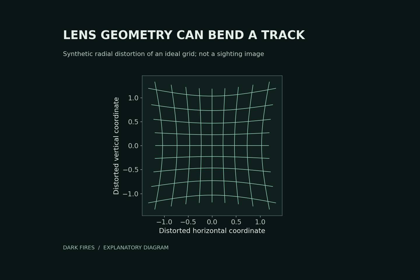
Our diagram applies a hypothetical radial mapping to a square grid. It illustrates geometric displacement only. It is not a UAP photograph and does not show how much distortion any particular camera has.
Measure the camera, not the desired answer
Calibration uses observations of a known pattern to estimate camera parameters and distortion coefficients. OpenCV’s example uses multiple views of a calibration target, then applies the estimated correction to images.
For a sighting analysis, retain the unmodified recording and document which camera configuration the calibration represents. Do not tune a correction until the unexplained track becomes straight: that would build the desired conclusion into the measurement.
Compare corrected and uncorrected positions, report calibration residuals, and propagate remaining position uncertainty into any velocity estimate. Even a well-calibrated pixel trajectory still needs distance and viewing geometry before it yields a physical speed.
Lens calibration addresses image geometry. It does not by itself correct camera movement, identify the object or prove that an apparent maneuver was an artifact.
Primary technical source: OpenCV camera calibration tutorial.
Generated illustration. Original Dark Fires schematic of hypothetical radial distortion, not recorded evidence.
Leave a Reply